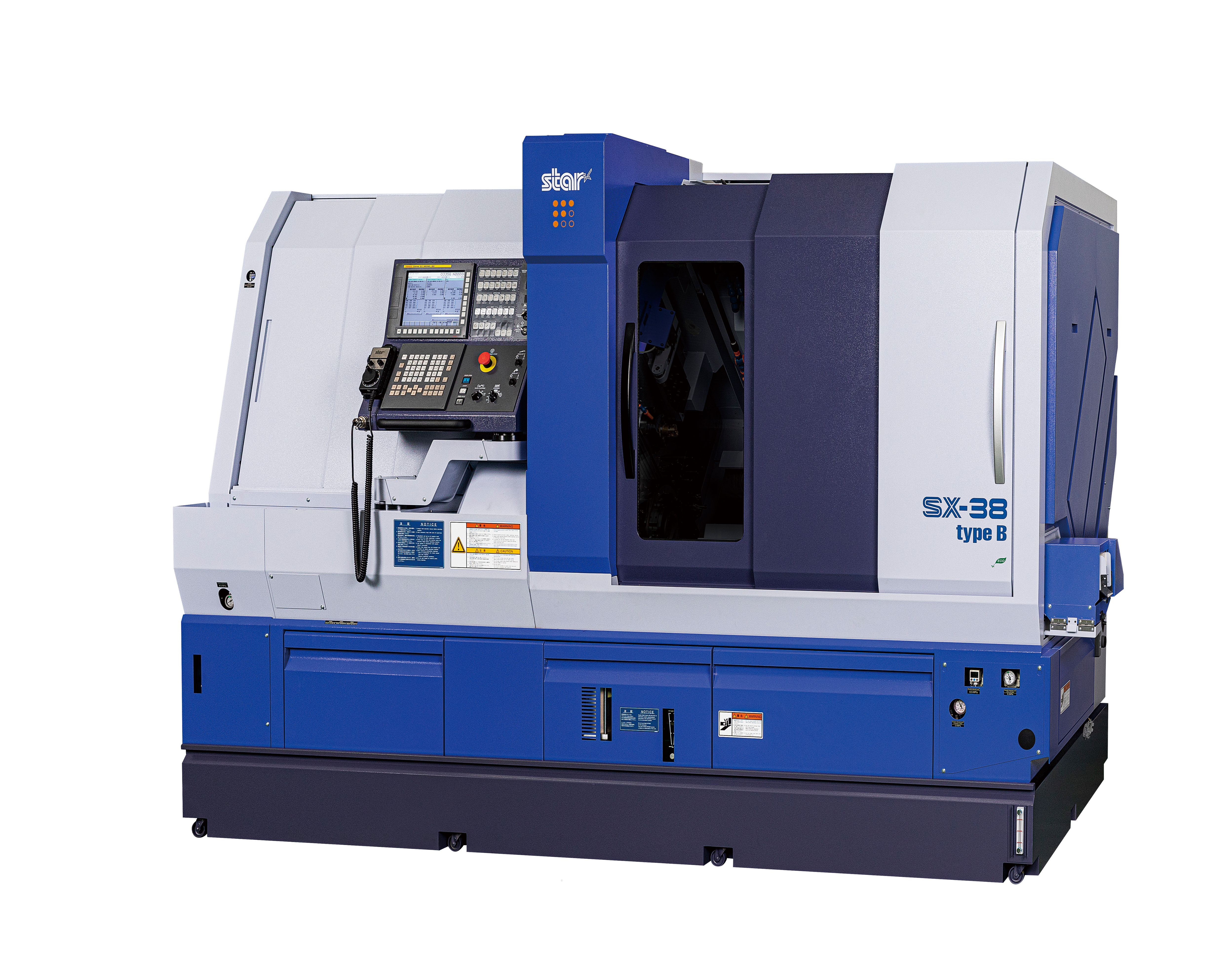
Machine Specifications
Specifications
Control, capacity & movement MM/IN
- Controller
- Fanuc 31i-B5
- Axes (Rapid Feed Rate)
- X1, X2, X3, Y1, Z1, Z2, Z3 (30 m/min)
Y2 (24 m/min) | Y3 (15 m/min)
B1 (27,000 deg/min)
C1, C2 (198,000 deg/min) - Maximum Capacity
- GB: 38 mm (1.5")
NON-GB: 42 mm (1.625") - Stroke
- GB: 320 mm (12.6")
NON-GB: 95 mm (3.740") - Dimensions
- 2955 x 1430 x 2005 mm
(approx. 117" x 57" x 79") - Center Height
- 1150 mm
(45.276") - Weight
- 5800 kg
(12787 lbs) - Coolant Tank Capacity
- 375 L
(100 gal)
Spindle & power-driven tooling RPM/KW
- Main Spindle
- 7,000 RPM
11.0 kW / 7.5 kW (cont.) - Power Driven Tools for Main
- Gang 6,000 RPM | Turret 6,000 RPM
Gang 3.0 kW / 2.2 kW | Turret 4.0 kW / 2.7 kW - Sub Spindle
- 7,000 RPM
11.0 kW / 7.5 kW (cont.) - Power Driven Tool for Sub
- 5,000 RPM
1.8 kW / 1.2 kW (cont.)
Tool Layout
Standard Tool Layout Included
- Work Holding
- S38 (TF48) | S38 (STM38)
- Tool Layout
- 4-Station Tool Holder 16mm (5/8") | 20mm Cutoff
4-Spindle Tilting Drill Unit with B-axis ER20/ER16
10-Station Turret
8-Spindle Unit for Back Working with Drive Unit
• All Cartridge positions available
Optional Tool Holders Options
- Options for Main Side
- 2-Station Tool Holder
Triple Sleeve Holders
Deep Hole Sleeve Holders
Drill Sleeves and Boring Bar Sleeves
Drilling/Milling Units
2-Spindle Front Drilling Unit
2-Spindle Skewed Hole Drilling Unit
High Speed 2-Spindle Cross Drilling Unit ER11
Thread Whirling Unit
Polygon Unit
Slotting Unit
Hobbing Unit - Options for Sub Side
- Drill Sleeves and Boring Bar Sleeves
Drill Sleeves with Internal Coolant
Drilling/Milling Units
4x Speed Type Drilling Unit
Cross Drilling Unit (max 3)
Slotting Unit
Accessories
Standard Accessories Included
- Guide Bushing / Non-Guide Bushing Conversion
- Automatic Centralized Lubrication Unit with level detector
- Pneumatic Unit
- Hydraulic Unit
- Spindle Cooling Unit
- Extended Coolant Tank (99gallon) with Coolant Level Detector
- Coolant Flow Detector [2B459]
- Door Interlock System
- Broken Cut-Off Tool Detector
- C-axis Contour Control (for the main/sub spindles)
- Spindle Clamp Unit (for the main/sub spindles)
- Parts Ejector with Spring [1T478]
- Parts Ejection Detector [1A409]
- Parts Conveyor
- Electronic Handwheel
- Beacon Interface [1T428]
- LAN/RS232C Interface
- Automatic Bar Feeder Interface
- Automatic Bar Feeder Interface 2 [1T419]
- Chip Conveyor Interface 20 Contacts Version [1T442]
- Coolant Unit Signal Cable 46 Contacts Version [1T439]
- Coolant Unit 0.7MPa (through Sub Spindle) [1T455]
- Coolant Unit Piping for Tool Holder [1T464]
- Coolant Piping for Guide Bush [1T466]
- Coolant Piping for Back 8 Spindle Unit [1T467]
- Coolant Piping for Back 8 Spindle Oil Hole [1T468]
- Coolant Piping for Tool Holder - x2 [1T469]
- Coolant Piping for Turret [1T465]
- 3 Sp. Holder for High Speed Drill with HP [10138]
Optional Accessories Options
- Beacon Light
- Main/Sub/Guide Bush Reductions Systems
- Magic Guide Bushing Unit
- JBS Flexible Guide Bushing Unit
- Pneumatic Parts Ejector
- Long Parts Ejector Guide Tube
- Tool Presetter
- Chiller Unit
- High Pressure Pump
- Mist Collector
- Chip Conveyor
- Fire Suppression System
- Bar Feeders
Functions
Standard Functions Included
- Control unit (FANUC Series 31i-B5)
- Operation panel (10.4" color LCD display)
- Number of control axes : 12 total (5 on Path1, 4 on Path2, 3 on Path3)
- Synchronized axis control (X1/X3, Y1/Y3, Z1/Z3, Z1/Z2, C1/C2)
- Synchronous rotation/phase control of Main & Sub Spindles
- Cs contour control (Main & Sub Spindle)
- Program storage : 8MB in total
- Number of registerable programs : 1000 in total
- Tool wear offset : 66 on each Path
- Automatic collet adjustment function
- Guide Bush / Non Guide Bush change function
- Spare M code (6 pairs)
- Increment system 1/10
- Tool life management function
- Cylindrical interpolation (G107)
- Polar coordinate interpolation (G112)
- Polygon machining (G251)
- Helical interpolation
- 3D coordinate conversion
- Motion Control - Optimization
- High Speed Smooth TCP
Optional Functions Options
- HFT Chip Control Technology
- SCP Chip Control Technology
- Circular Thread Cutting
- Flexible Synchronization Control