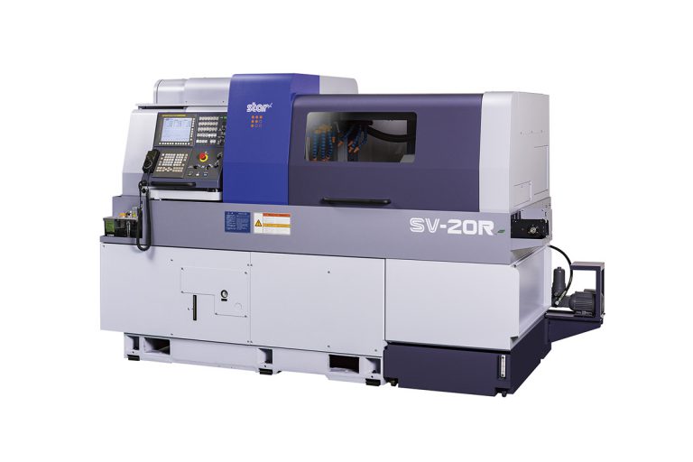
-
Max. Machining Diameter
ø20mm (25/32in) OP: ø23mm (29/32in)
-
Max. Headstock Stroke
STANDARD
205mm (8in)
R.M.G.B Type
160mm(6-19/64in) : OP
N.G.B. Type
Bar diameterx2.5 (Max. 50mm) (Max. 1-31/32in) -
Tool Post Configuration
GANG TYPE
Turning tool + Power-driven tool
TURRET TYPE
8 stations -
Tool
NUMBER OF TOOLS
Gang Type
6 tools (16mm), 7 tools (12mm)
Turret Type
1 tool / station (16mm), Max. 3 tools / station (12mm) -
Sleeve
NUMBER OF TOOLS
Max. 3 tools/station
MAX. DRILLING CAPABILITY
ø14mm (35/64in)
MAX. TAPPING CAPABILITY
M12 x P1.75 -
Power Driven Attachment
NUMBER OF TOOLS
Gang Type
5 tools
Turret Type
Max. 2 tools / station (mountable at each 8 positions)
MAX. DRILLING CAPABILITY
Gang Type & Turret Type
ø10mm(25/64in)
MAX. TAPPING CAPABILITY
Gang Type & Turret Type
M8 x P1.25
SPINDLE SPEED
Gang Type
Max. 8,000min-1
Turret Type
Max. 5,750min-1
DRIVE MOTOR
Gang Type
2.2kW
Turret Type
2.7kW(continuous) / 4.0kW(5min. / 30%ED) -
Rapid Feed Rate
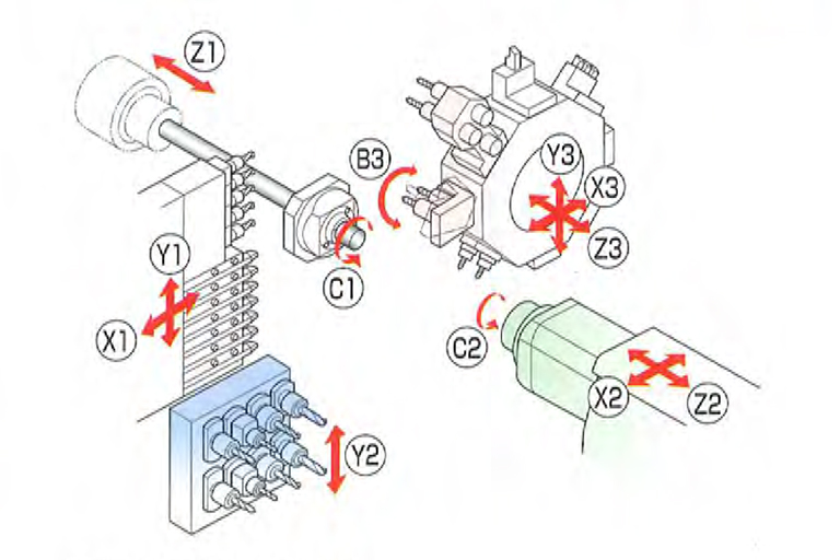
30m/min(X1, X2, X3, Y1, Z1, Z2, Z3)
20m/min(Y2), 15m/min(Y3) -
Main Spindle Indexing Angle
C-axis control
-
Main Spindle Speed
Max.10,000min-1
-
Main Spindle Motor
3.7kW(continuous) / 5.5kW (10min. / 60%ED)
-
Coolant Tank Capacity
220ℓ
-
Dimension (W x D x H)
2,730 x 1,350 x 1,865mm
-
Center Height
1,125mm
-
Weight
4,150kg
-
Power Consumption
6.3KVA
- Standard Machine Specifications
- Backworking Attachment Specifications
- Standard Accessories and Functions
- Optional Accessories and Functions
-
Max. Chucking Diameter
ø20mm (25/32in) OP: ø23mm (29/32in)
-
Max. Length For Front Ejection
105mm (4-9/64in)
-
Max. Part Projection Length
75mm (2-16/64in)
-
Back 8-Spindle Unit
NUMBER OF TOOLS
Stationary tool
8 tools
Power driven tool
Max. 8 tools
MAX. DRILLING CAPABILITY
Stationary tool
ø12mm (1/2in)
Power driven tool
ø6mm (15/64in)
MAX. TAPPING CAPABILITY
Stationary tool
M10 x P1.5
Power driven tool
M5 x P0.8 -
Power-Driven Att. Spindle Speed
Max. 8,000min-1
-
Power-Driven Att. Drive Motor
1.0kW (continuous) / 1.2kW (5min./30%ED)
-
Sub-Spindle Indexing Angle
C-axis control
-
Sub-Spindle Speed
Max. 10,000 min-1
-
Sub-Spindle Motor
2.2kW (continuous) / 3.7kW (10min./40%ED)
- CNC unit FANUC 31i-B5
- Power electric & Operation panel & 10.4-inch color LCD
- Pneumatic unit
- Hydraulic unit
- Spindle cooling unit
- Automatic centralized lubrication system (with level detecting function)
- Cutting oil level (lower limit) detecting unit
- Door interlock system
- Broken cutoff tool detector
- C-axis control (Main/Sub)
- Spindle clamp unit (Main / Sub)
- Drive unit for revolving guide bush
- Revolving guide bush unit
- Main/Sub collet
- Air purge for revolving guide bush
- Sub spindle air purge unit
- Tool holder (Gang-type tool post)
- 5-spindle milling unit (Gang-type tool post)
- Drive system for power-driven attachment (Turret-type tool post)
- Back 8-Spindle unit
- Drive system for power-driven attachment B (Back 8-spindle unit)
- Parts conveyor
- Automatic bar feeder interface
- RS-232C interface
- Work light (for cutting chamber and headstock chamber)
- Leakage breaker
- Coolant flow detector
- Parts ejection detector
- Water removal unit
- Oil mist filter
- Beacon
- Non-guide bush type
- Rotary magic guide bush unit
- For pneumatic unit rotary magic guide bush
- Main spindle inner tube
- Parts ejector (Air cylinder type)
- Parts ejector (Spring type)
- Parts ejector with guide tube
- Parts stopper unit
- Coolant unit(6.9MPa / 2.5MPa / 0.7MPa)
- Coolant unit signal cable
- Coolant unit power cable
- Coolant valve
- Coolant pipings
- Manual pulse generator
- Transformer CE marking version
- CE marking version
- Tool Presetter